OPEN END SPINNING SYSTEM:
The open - yarn spinning method has a comparatively low manufacturing cost.
Since many processes in this yarn manufacturing process get bypassed so that the cost of production gets reduced comprehensively.
The second thing is the package size obtained in the open-end spinning method. The large package size results in this spinning method. There is no need to enlarge it. Thus the cost of production gets reduced.
This spinning method is useful for coarse count yarn.
The open end yarn poses poor tensile strength due to a lower degree of fiber parallelization in the yarn.
The productivity of this method is high in comparison to the ring-spinning method.
ROTOR SPINNING SYSTEM:
Rotor spinning is the most wide system in the open-end yarn manufacturing industry. It has all the necessary requirements for an efficient spinning method. The open-end spinning has some limitations. It is not suitable for spinning fine count yarn. More bulkiness results in the open end yarn in this process. The high twist multiplier gets employed in this method.
The open end yarn poses good abrasion resistance. This is the special character of open-end yarn getting produced in rotor spinning. The open end yarn consists of wrapped fibres around the yarn surface. The open end yarn also contains a thin outer layer of fibers with hardly any twist or even with twist in the reverse direction. The new fibres get joined on to the already well-twisted fibre strand during each rotation of the rotor. These latecomers receive only a fraction of the desired twist level. If this low twist is lower than the false-twist, the fibres get twisted in the reverse direction.
The open end yarn poses good abrasion resistance. This is the special character of open-end yarn getting produced in rotor spinning. The open end yarn consists of wrapped fibres around the yarn surface. The open end yarn also contains a thin outer layer of fibers with hardly any twist or even with twist in the reverse direction. The new fibres get joined on to the already well-twisted fibre strand during each rotation of the rotor. These latecomers receive only a fraction of the desired twist level. If this low twist is lower than the false-twist, the fibres get twisted in the reverse direction.

STRUCTURE AND WORKING OF ROTOR SPINNING MACHINE:
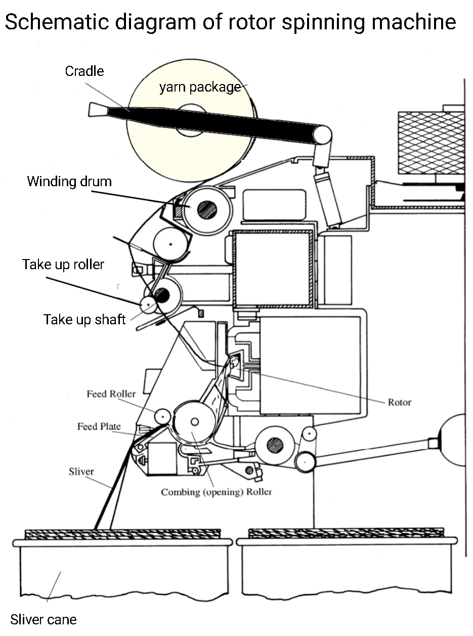
The sliver obtained from carding or draw frame is used as feed material for the open-end spinning. The working of rotor spinning can be understood in the below steps:
Sliver feeding assembly:
The function of the feeding system is to pass the sliver from the sliver can to the fibres opening assembly. First of all the sliver passes over the guide then the feed roller. The feed roller carries forward the material to the feed table. The rotating feed roller helps to grip the sliver and carries it forward over the feed table into the opening roller. The feed table is equipped with spring-loaded pressure which ensures strong gripping of the fed sliver toward the feed roller. This assembly gets equipped with automatic stop motion. When sliver a yarn end down, sliver feeding gets stopped immediately by disengaging of feed clutch. The feed roller also stops to rotate. The signal pulse causing this is generated by a yarn-sensing device called a thread monitor.
The function of the feeding system is to pass the sliver from the sliver can to the fibres opening assembly. First of all the sliver passes over the guide then the feed roller. The feed roller carries forward the material to the feed table. The rotating feed roller helps to grip the sliver and carries it forward over the feed table into the opening roller. The feed table is equipped with spring-loaded pressure which ensures strong gripping of the fed sliver toward the feed roller. This assembly gets equipped with automatic stop motion. When sliver a yarn end down, sliver feeding gets stopped immediately by disengaging of feed clutch. The feed roller also stops to rotate. The signal pulse causing this is generated by a yarn-sensing device called a thread monitor.

Fibres opening assembly:
Since a very little amount of twist gets employed to carded or drawn sliver to hold the fibres together so that it needs to open the fibres completely. The opening action gets performed with the help of a combing roller in the rotor spinning machine. This roller gets covered with saw tooth wire clothing. When the sliver gets passed through a rotating combing roller, the individual opening of fibres takes place. The fibre to fibre opening of material is necessary before it enters the drafting assembly.
Since a very little amount of twist gets employed to carded or drawn sliver to hold the fibres together so that it needs to open the fibres completely. The opening action gets performed with the help of a combing roller in the rotor spinning machine. This roller gets covered with saw tooth wire clothing. When the sliver gets passed through a rotating combing roller, the individual opening of fibres takes place. The fibre to fibre opening of material is necessary before it enters the drafting assembly.

Fibres drafting zone:
In the drafting zone, the fibres get further opened. The parallel arrangement of fibres also gets performed. When the fibres get opened completely, these fibres are sucked with the help of a transport tube. An air current flows in this tube which carries the opened fibres to the rotating rotor. These fibres get accumulated on the inside wall of the rotor. The air current is produced by the main duct in the section and then through a vacuum in the rotor housing. A central fan is used to create a vacuum. This fan draws air by suction through small ducts from each rotor housing. To facilitate the generation of this negative pressure, the rotor box must be hermetically sealed as far as possible. The suction current in the fibre channel helps to pick off the fibres from the surface of the opening roller and send them into the rotor. In the course of this movement, both the air and the fibres are accelerated due to the converging shape of the feed tube. This represents a second draft following the nip trough/opening roller and results in further separation of the fibres. The fibres are straightened in this air current. A third draft creates upon the arrival of the fibres on the wall of the rotor. Since the peripheral speed of the rotor is many times greater than the speed of the fibres, the parallelization of fibres takes place in this zone. The arrangement of fibres improves. When the fibres slide down the wall of the rotor into the rotor groove due to the high centrifugal force generated within the rotor. The fibres are straightened finally here.
In the drafting zone, the fibres get further opened. The parallel arrangement of fibres also gets performed. When the fibres get opened completely, these fibres are sucked with the help of a transport tube. An air current flows in this tube which carries the opened fibres to the rotating rotor. These fibres get accumulated on the inside wall of the rotor. The air current is produced by the main duct in the section and then through a vacuum in the rotor housing. A central fan is used to create a vacuum. This fan draws air by suction through small ducts from each rotor housing. To facilitate the generation of this negative pressure, the rotor box must be hermetically sealed as far as possible. The suction current in the fibre channel helps to pick off the fibres from the surface of the opening roller and send them into the rotor. In the course of this movement, both the air and the fibres are accelerated due to the converging shape of the feed tube. This represents a second draft following the nip trough/opening roller and results in further separation of the fibres. The fibres are straightened in this air current. A third draft creates upon the arrival of the fibres on the wall of the rotor. Since the peripheral speed of the rotor is many times greater than the speed of the fibres, the parallelization of fibres takes place in this zone. The arrangement of fibres improves. When the fibres slide down the wall of the rotor into the rotor groove due to the high centrifugal force generated within the rotor. The fibres are straightened finally here.
Cleaning assembly:
Most of the transport air enters only at the trash removal slot and only a small amount through the draw-off tube. One result of the centrifugal force of the opening roller is that impurities carried with the incoming sliver are expelled through an outlet of the opening roller housing. The expelled waste falls onto a conveyor belt, which carries it either to one or to both ends of the spinning machine, where it is removed by suction nozzles on each side of the machine.
Fibre condensating system:
When the rotor revolves at a very high speed, a centrifugal force gets generated. This centrifugal force causes the fibres to collect in the groove of the rotor. A ring of fibres forms in the rotor groove. This fibre ring is then swept from the rotor continuously by a newly formed yarn, which contains untwisted fibres.
Twisting ( twist insertion)

Twist insertion in this spinning process is performed by means of a rotor. This rotor revolves at a very high speed. The rotor can achieve the maximum rpm of 140000. Each revolution of rotor inserts one turn in the yarn.

The yarn gets produced is pulled out of the rotor with the help of the navel continuously. If nothing further were done, the rotor would be choked in no time. However, since the whole purpose is to form these fibres into a new yarn, the free end of the yarn is allowed to extend from the rotational axis to the rotor periphery. The centrifugal force (more than 100 000 times the weight of the fibre) acting at this point presses the yarn end firmly against the wall of the collecting groove, exactly as in the case of the fibres in the ring. The yarn end, therefore, adheres to the rotor wall. As the rotor turns, it, therefore, carries the yarn along, and the latter rotates around the nozzle like one arm of a crank. Each revolution of the rotor generates one turn of genuine twist in the yarn. When the yarn has reached its maximum twist level as determined by the prevailing force conditions, the yarn end begins to turn about its own axis, i.e., it rolls in the rotor groove. Now the open yarn end is resting in the binding-in zone on a strand of parallel fibres; rolling of the yarn end, therefore, causes the brush-like yarn end to grasp fibres from the ring and twist them in to give a new yarn portion, which proceeds to grasp the next fibres and twist them in, and so on. A yarn is thus spun continuously. It is simply necessary to pull this yarn out of the rotor via yarn compensation bar by means of take-off rollers and wind it up on a winding drum into the cross-wound package
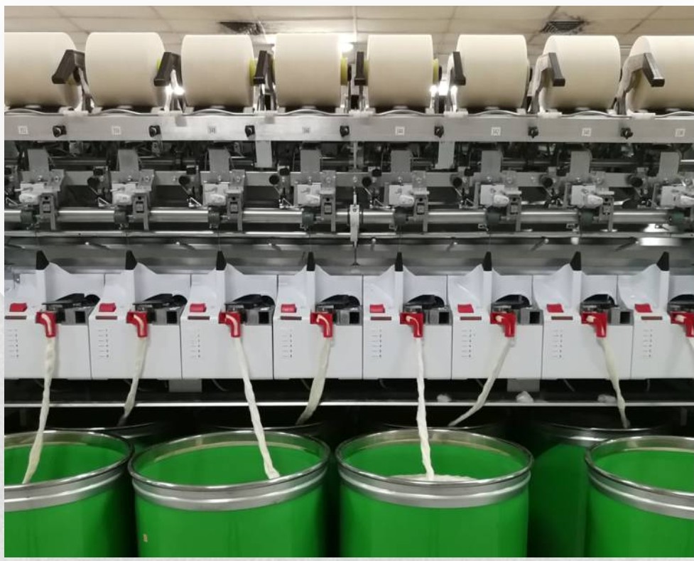
Winding ( yarn package building):
The yarn is then taken up onto a cross-wound package, thus separating the winding process from twisting. Yarn is wound onto packages ready for use in fabric formation the yarn is a lot cheaper to produce.
Please click on the below video link to watch the full article in Hindi:
Please click on the below video link to watch the full article in Hindi:
You may also be interested in the following articles:
Various types of spinning methods
Air - jet /vortex spinning method ( an open end yarn spinning process)
Yarn count determination from fabric swatch or count determination from short length of yarn
Advantages and disadvantages of open end yarn
Advantages and disadvantages of ring frame process
You may also be interested in below sponsored links:
You may also be interested in the below articles:
AIRJET/ VORTEX SPINNING METHOD (A OPEN END SPINNING PROCESS)


Nice explanation on rotor spinning. You can takerotor spinning book.
ReplyDeleteDoes rotor spinning department needs a chiller for aircondition?
ReplyDelete